
AEROPROPSIM / RESEARCH COMPARISON
PROWIM — Propeller–Wing Interaction Validation
How does propeller rotation change spanwise wing loading?
This AeroPropSim study compares a powered rectangular wing with published wind-tunnel data for the Beaver propeller at 0° and 4° angle of attack. A phase-mean prescribed wake feeds a horseshoe vortex-lattice wing model through steady, one-way coupling.
The archived case uses a 49.5 m/s freestream, advance ratio J = 0.85 and a four-bladed Beaver propeller at approximately 14,743 RPM. The primary wake is averaged over eight samples per blade passage before the wing solve.
Geometry & prescribed wake
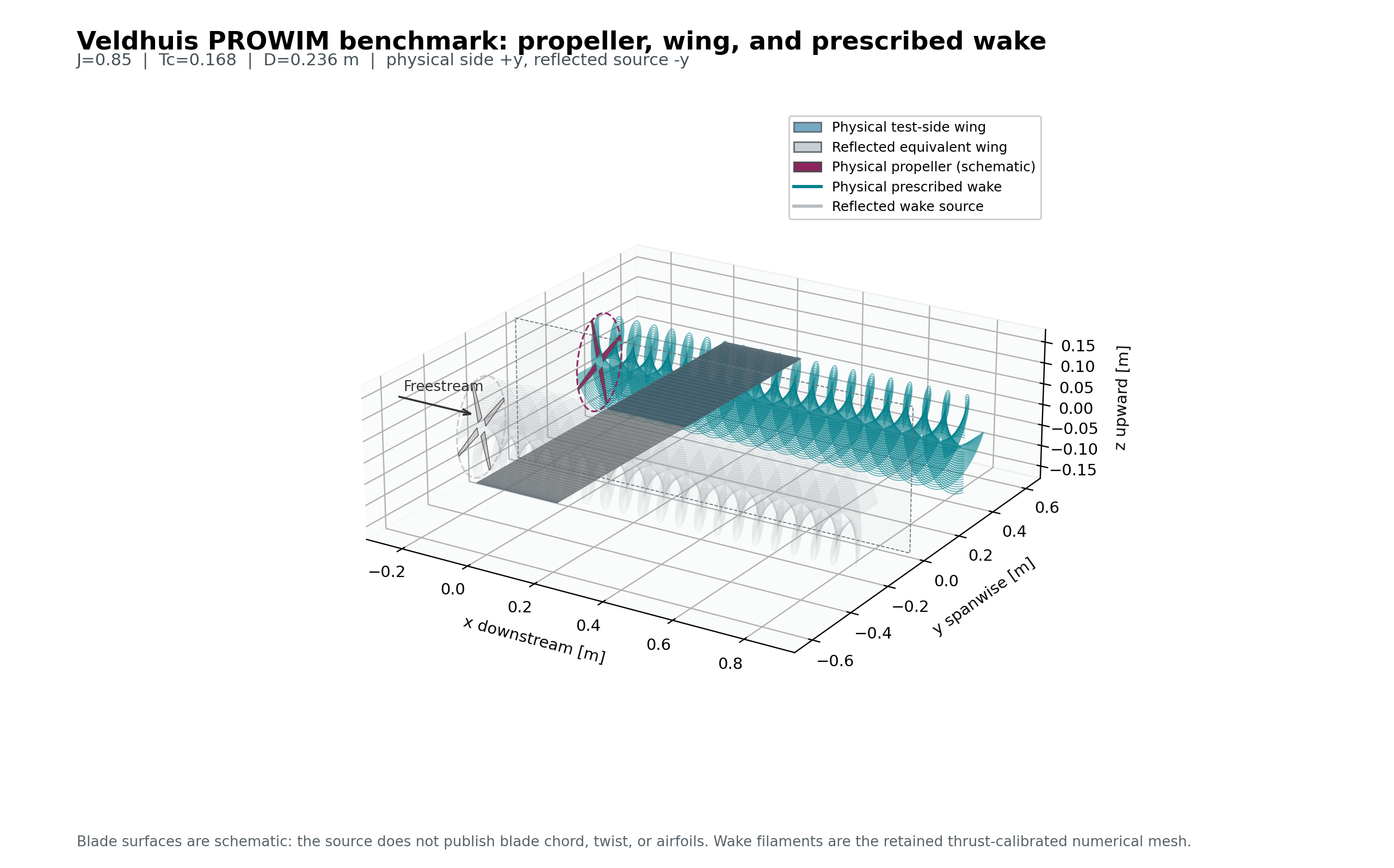
- Physical test-side wing
- Reflected equivalent wing
- Physical propeller
- Physical prescribed wake
- Reflected wake source
Experimental comparison at 0° & 4°
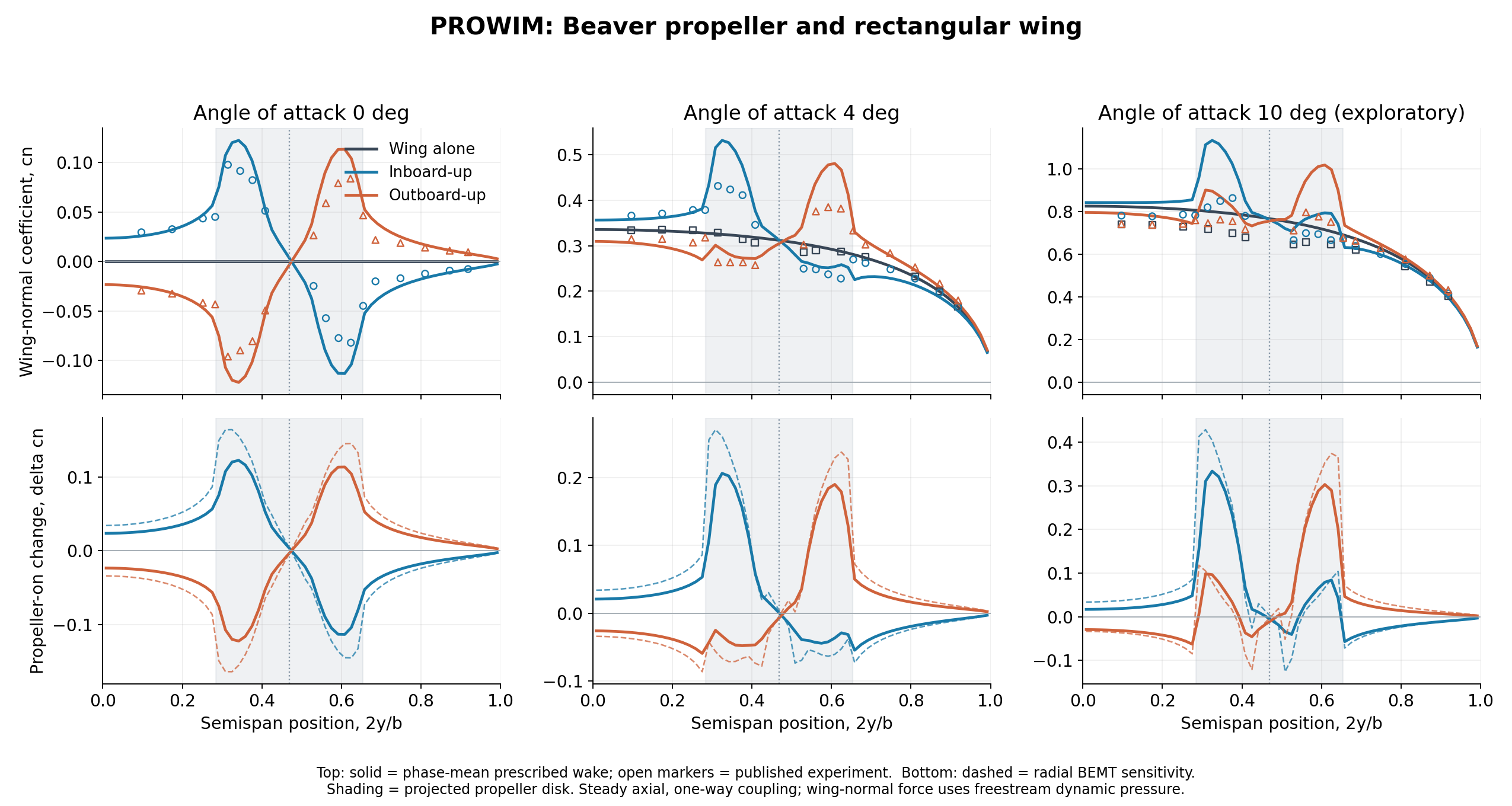
Top: wing-normal coefficient cₙ. Solid curves show the phase-mean prescribed-wake model; open markers show published experiment. Grey: wing alone. Blue: inboard-up. Orange: outboard-up.
Bottom: propeller-on change Δcₙ. Dashed curves show radial BEMT sensitivity. Shading indicates the projected propeller disk; the dotted line marks its centre.
Steady axial, one-way coupling. Wing-normal coefficients use freestream dynamic pressure. This research comparison reproduces the selected panels from the supplied figure; models and validation continue to evolve.
What the comparison shows
The model and experiment show redistribution of loading near the propeller disk, with opposite redistribution patterns at 0° for the two rotation directions. The lower panels isolate the change due to propeller operation and show sensitivity to the wake representation.
The results are specific to the selected conditions and prescribed wake model. The model overpredicts local peaks, and the digitised experimental markers do not provide a full measurement uncertainty. This comparison cannot establish full-aircraft X-57 accuracy.
References
- Alvarez and Ning, figures 28–29Published geometry and comparison, including Veldhuis’s wind-tunnel measurements.
- Clarke, Erhard and Alonso, figures 5–6Corroborating geometry, test conditions and rotation conventions.